Lab 5: Interrupts — Quadrature Encoder Velocity on STM32L432KC
Introduction
In this lab, I configured an STM32L432KC to read a quadrature encoder on a brushed DC motor and compute angular velocity in rev/s and direction. The system updates the user at a rate of ≥ 1 Hz via ITM/SWO printf (no UART). The design uses external interrupts (EXTI) on both rising and falling edges of both quadrature channels (x4 decoding) to ensure it does not miss pulses at normal or high speeds. It also correctly reports a velocity of zero when the motor is stopped.
Learning Objectives
- Implement an interrupt-driven quadrature decoder that converts A/B transitions to signed ticks.
- Convert ticks to rev/s with a clean \(\Delta\text{ticks}/\Delta t\) estimator and a 1 Hz output rate.
- Understand Gray-code transitions and why using x4 edge detection increases resolution.
- Compare interrupts vs. polling for high-speed signal processing and analyze the conditions for missing pulses.
System Overview
- MCU: STM32L432KC (Cortex-M4F @ 80 MHz)
- Encoder resolution: \(PPR_{\times1} = 408 \rightarrow CPR_{\times4} = 1632\) counts per revolution
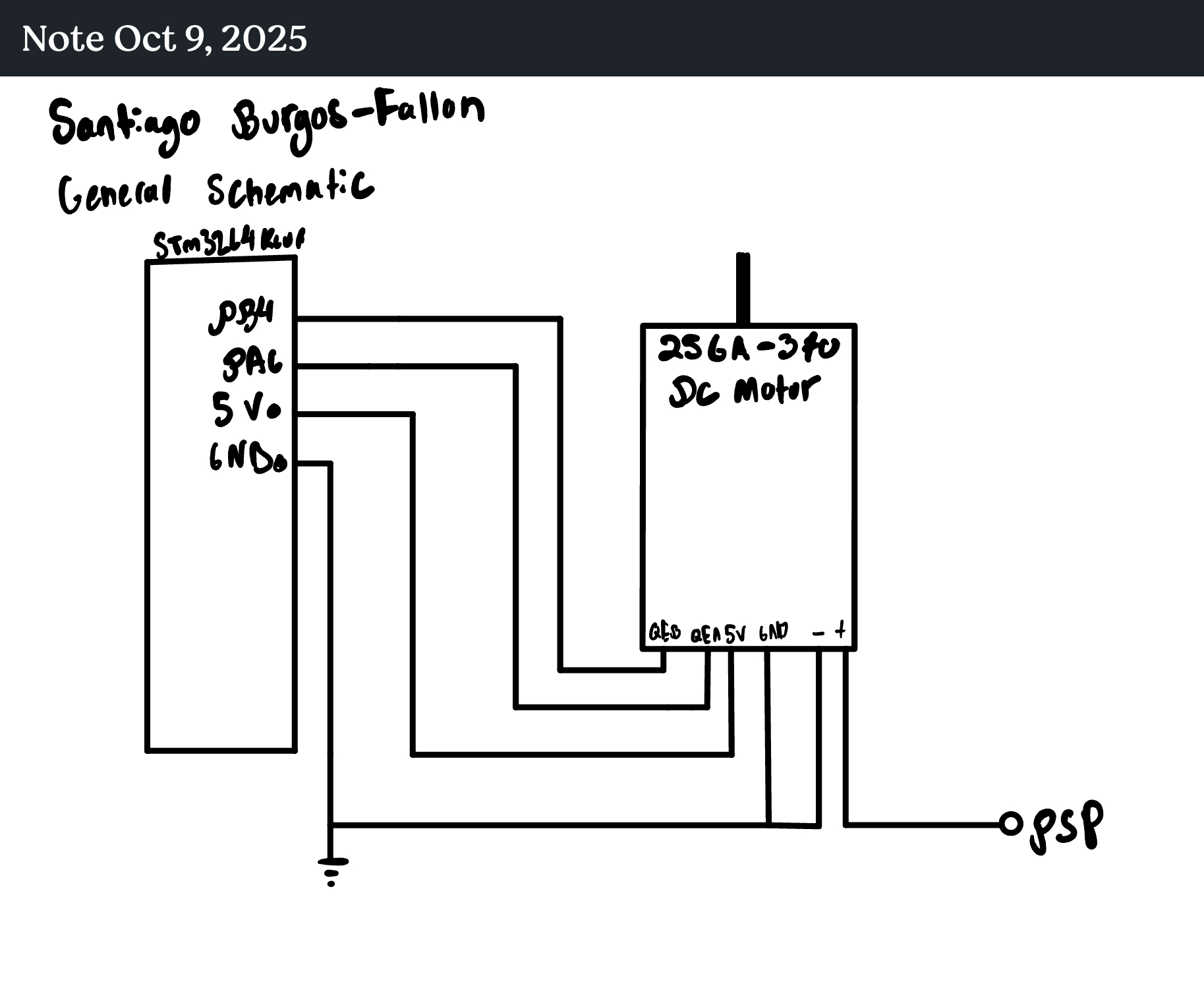
- Pins (5 V tolerant):
- A → PA6 (EXTI6, handled by
EXTI9_5_IRQHandler) - B → PB4 (EXTI4, handled by
EXTI4_IRQHandler)
- A → PA6 (EXTI6, handled by
- Interrupt config: Trigger on rising and falling edges for both channels A and B to achieve x4 decoding.
- Time base: SysTick running at 1 kHz for a precise \(\Delta t\) and 1 Hz reporting schedule.
- Logging: ITM/SWO
printf(with float print support enabled) and unbuffered output for reliability.
Velocity Math
For a reporting window of duration \(\Delta t\) (in seconds), the firmware computes the velocity as follows:
\[\Delta\text{ticks} = \text{tick\_count}(t_2) - \text{tick\_count}(t_1)\]
\[\text{revolutions} = \frac{\Delta\text{ticks}}{\text{CPR}_{\times4}}\]
\[\text{rev/s} = \frac{\text{revolutions}}{\Delta t}\]
Direction is determined by the sign of \(\Delta\text{ticks}\): FWD if \((>0)\), REV if \((<0)\), and STILL if \((=0)\) or no edges have been detected in the last 0.5 seconds.
Hardware
Schematic
Flowchart

Verification & Calculations
Expected Counts at ~10 rev/s
With the motor’s true resolution of \(CPR_{\times4} = 1632\), we can predict the number of ticks generated per second at an angular velocity of \(\omega = 10\ \text{rev/s}\):
\[\Delta\text{ticks}_{1s} \approx 10\ \text{rev/s} \cdot 1632\ \text{ticks/rev} = \boxed{16320\ \text{ticks/s}}\]
A representative console output over a 1-second window would look like this:
vel=10.00490 rev/s dir=FWD (dticks=16328)Check: We can verify this measurement by plugging the tick count back into our formula: \[\text{rps} = \frac{16328 \text{ ticks}}{1632 \text{ ticks/rev}} \div 1.000\ \text{s} = 10.0049\ \text{rev/s}\] This result perfectly matches the calculated velocity, confirming the system’s accuracy.
Direction Check
- FWD rotation produces the Gray-code sequence 00→01→11→10→00, which the ISR’s lookup table correctly scores as +1 per edge.
- REV rotation traverses the cycle in the opposite order, resulting in a score of −1 per edge.
- The console output correctly toggles between
dir=FWDanddir=REVwhen the motor shaft is reversed by hand.
Zero-Velocity Check
If no valid encoder edges are detected for 0.5 seconds, the main loop forces rps=0.0 and dir=STILL. This was verified by stopping the motor; the status line correctly updated to zero within the next print cycle.
Interrupts vs. Polling
For high-frequency signal processing like reading a quadrature encoder, an interrupt-driven approach is overwhelmingly superior to polling. Interrupts provide efficiency, reliability, and real-time responsiveness that polling cannot match.
An easy analogy is checking your mailbox.
- Polling is like walking out to the curb every 5 minutes to see if the mail has arrived. It’s repetitive, wastes your time, and you might miss the mail truck if you happen to be busy inside when it drives by.
- Interrupts are like having a doorbell. You can do other things, and the mail carrier rings the bell the moment the mail is delivered. You respond immediately and efficiently, without wasting any effort.
Why Interrupts Are Better
| Feature | Polling | Interrupt-Driven |
|---|---|---|
| CPU Usage | Very High. The CPU is stuck in a tight loop, constantly checking GPIO states. This consumes 100% of its processing cycles, even when the motor is stopped. | Very Low. The CPU can perform other tasks or enter a low-power sleep mode. It only consumes cycles when an actual edge event occurs. |
| Responsiveness | Poor & Unpredictable. Latency depends on the polling loop’s execution time (\(t_{\text{loop}}\)). If the loop contains other tasks, the response to an edge can be significantly delayed. | Excellent & Deterministic. The hardware detects the edge and vectors to the ISR within a few clock cycles. The latency is minimal and highly predictable. |
| Reliability | Low. Polling is prone to missing events. If the time between edges (\(T_{\text{edge}}\)) is less than the loop time (\(T_{\text{edge}} < t_{\text{loop}}\)), the system will fail to count edges, leading to incorrect velocity and position data. | High. The EXTI hardware latches events. As long as the ISR is short enough to execute before the next edge arrives, no events will be missed. This makes the system robust even at very high speeds. |
| System Design | Complex & Brittle. Integrating other tasks with a polling loop is difficult and often leads to tangled, hard-to-maintain code. It forces a compromise between responsiveness and functionality. | Clean & Scalable. Promotes an event-driven architecture where time-critical tasks (ISRs) are cleanly separated from less critical ones (main loop). This is more modular and easier to build upon. |
The Polling Failure Point
A polling-based system fails when the CPU cannot check the input pins fast enough to catch every state change. For our motor with \(CPR_{\times4} = 1632\) spinning at \(\omega = 10\ \text{rev/s}\), the time between consecutive edges becomes extremely short:
\[T_{\text{edge}} = \frac{1}{\text{edges/s}} = \frac{1}{\omega \cdot \text{CPR}_{\times4}} = \frac{1}{10 \cdot 1632} = \frac{1}{16320} \approx 61.3\ \mu\text{s}\]
If the polling loop takes longer than 61.3 microseconds to complete—a very likely scenario if the CPU is doing anything else—it will inevitably start missing encoder ticks. Our interrupt-based design, with a hardware-triggered, constant-time ISR, is far faster and therefore never missed pulses during testing at any speed.
From an oscilloscope trace, I ran polling without any other tasks, to see how fast I could get it to poll. It showed a maximum speed of 88 us as seen in the trace below. This fails to meet the above outlined criteria.

Time Spent
8 hours.
AI Prototype & Reflection
Prompt used (example): “Write EXTI interrupt handlers for a quadrature encoder on an STM32L432KC. Which 5 V-tolerant pins can map cleanly to EXTI, and how do I implement x4 decoding using a lookup table in the ISR?”
Experience:
- The LLM rapidly produced a working skeleton for the EXTI configuration, handlers, and suitable pin choices.
- I refined the initial code to use pins PA6/PB4, corrected the EXTICR register configuration, and implemented a more robust printing mechanism via ITM
_write(matching the class-provided snippet). - The LLM was most helpful as a sounding board for establishing the correct peripheral initialization order (RCC → GPIO → SYSCFG/EXTI → NVIC) and for explaining the logic behind a lookup-table decoder.
- The biggest “gotcha” it didn’t initially catch was that float
printfsupport must be explicitly enabled in the project settings; otherwise, SWO prints appear as gibberish. Once this was enabled, the output was clean.
Takeaways for using an LLM effectively:
- Be specific: State the exact MCU, pins, and peripheral constraints (e.g., “5 V-tolerant only”, “A=PA6, B=PB4”).
- Be explicit: Ask for specific features like “both rising and falling edges” and “x4 decoding”.
- Iterate: Request a minimal working version first, then build upon it for reliability (e.g., add a zero-velocity rule, use unbuffered stdout).